Components
In this section we are introducing some of of the main elements we are going to use in the payload.
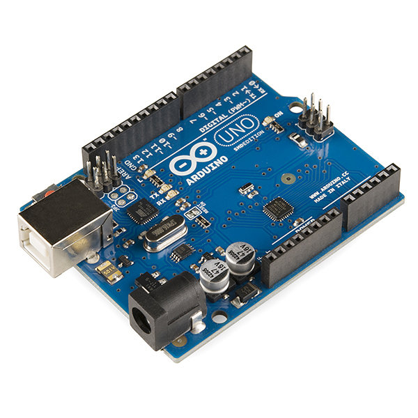
Arduino Uno
Arduino/Genuino Uno is a microcontroller board based on the ATmega328P. It has 14 digital input/output pins (of which 6 can be used as PWM outputs), 6 analog inputs, a 16 MHz quartz crystal, a USB connection, a power jack, an ICSP header and a reset button.
We will use this board as the main board of the payload. We will connect to this microcontroller all the rest of the components we will need to do the aforementioned measurements. All the technical specifications of this board are detailed in table on a right.
For more information about the Arduino Uno schematics there is a whole electrical layout at https://www.arduino.cc/en/uploads/Main/Arduino_Uno_Rev3-schematic.pdf
| Microcontroller | ATmega328P |
| Operating Voltage | 5V |
| Input Voltage (recommended) | 7-12V |
| Input Voltage (limit) | 6-20V |
| Digital I/O Pins | 14 (of which 6 provide PWM output) |
| PWM Digital I/O Pins | 6 |
| Analog Input Pins | 6 |
| DC Current per I/O Pin | 20 mA |
| DC Current for 3.3V Pin | 50 mA |
| Flash Memory | 32 KB (ATmega328P)of which 0.5 KB used by bootloader |
| SRAM | 2 KB (ATmega328P) |
| EEPROM | 1 KB (ATmega328P) |
| Clock Speed | 16 MHz |
| LED_BUILTIN | 13 |
| Dimentions | 53.4 mm x 68.6 mm |
| Weight | 25 g |
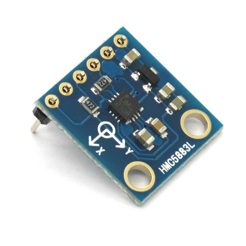
Magnetometer
The chosen magnetometer for the payload has been the HMC5883L model. The HMC5883L is a surface-mount, multi-chip module designed for low-field magnetic sensing with a digital interface for applications such as lowcost compassing and magnetometry. It includes high-resolution HMC118X series magneto resistive sensors plus an ASIC containing amplification, automatic degaussing strap drivers, offset cancellation, and a 12-bit ADC that enables 1° to 2° compass heading accuracy. The I2C serial bus allows for easy interface. The HMC5883L is a 3.0×3.0x0.9mm surface mount 16-pin leadless chip carrier (LCC).
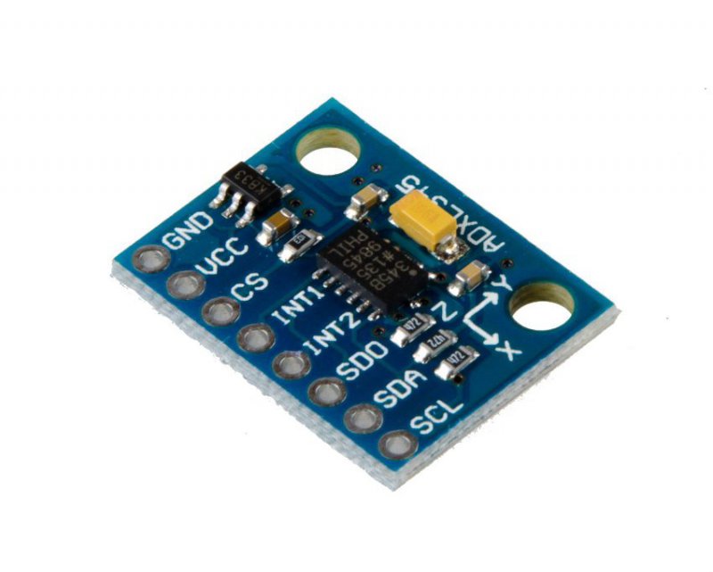
Accelerometer
The chosen accelerometer for the payload has been the ADXL345 model. It is a small, thin, low power, 3-axis accelerometer with high resolution (13-bit) measurement at up to ±16 g. Digital output data is formatted as 16-bit twos complement and is accessible through either a SPI (3- or 4-wire) or I2C digital interface. It measures the static acceleration of gravity in tilt-sensing applications, as well as dynamic acceleration resulting from motion or shock. Its high resolution (4 mg/LSB) enables measurement of inclination changes less than 1.0°.
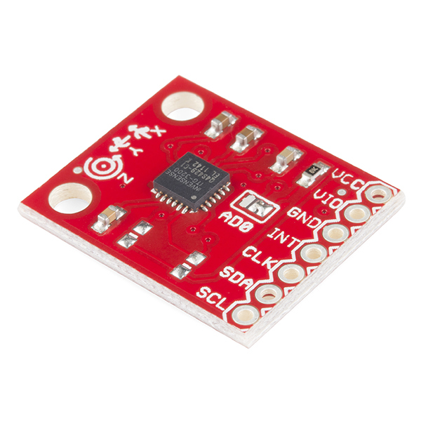
Gyroscope
The chosen gyroscope for the payload has been the ITG-3200 model. The ITG-3200 features three 16-bit analog-to-digital converters (ADCs) for digitizing the gyro outputs, a user-selectable internal low-pass filter bandwidth, and a Fast-Mode I2C (400kHz) interface. Additional features include an embedded temperature sensor and a 2% accurate internal oscillator.
The ITG-3200 can be powered at anywhere between 2.1 and 3.6V. For power supply flexibility, the ITG-3200 has a separate VLOGIC reference pin (labeled VIO), in addition to its analog supply pin (VDD) which sets the logic levels of its serial interface. The VLOGIC voltage may be anywhere from 1.71V min to VDD max. For general use, VLOGIC can be tied to VCC. The normal operating current of the sensor is just 6.5mA.